/***************************************************************************************
* Lin_Enc_02.ino 05-12-2014 unix_guru at hotmail.com @unix_guru on twitter
* http://arduino-pi.blogspot.com
*
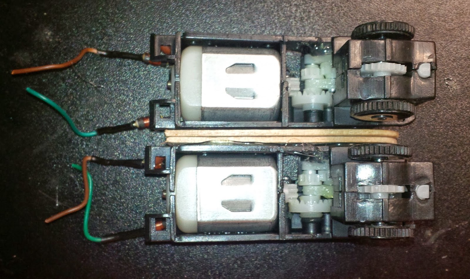
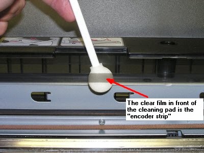
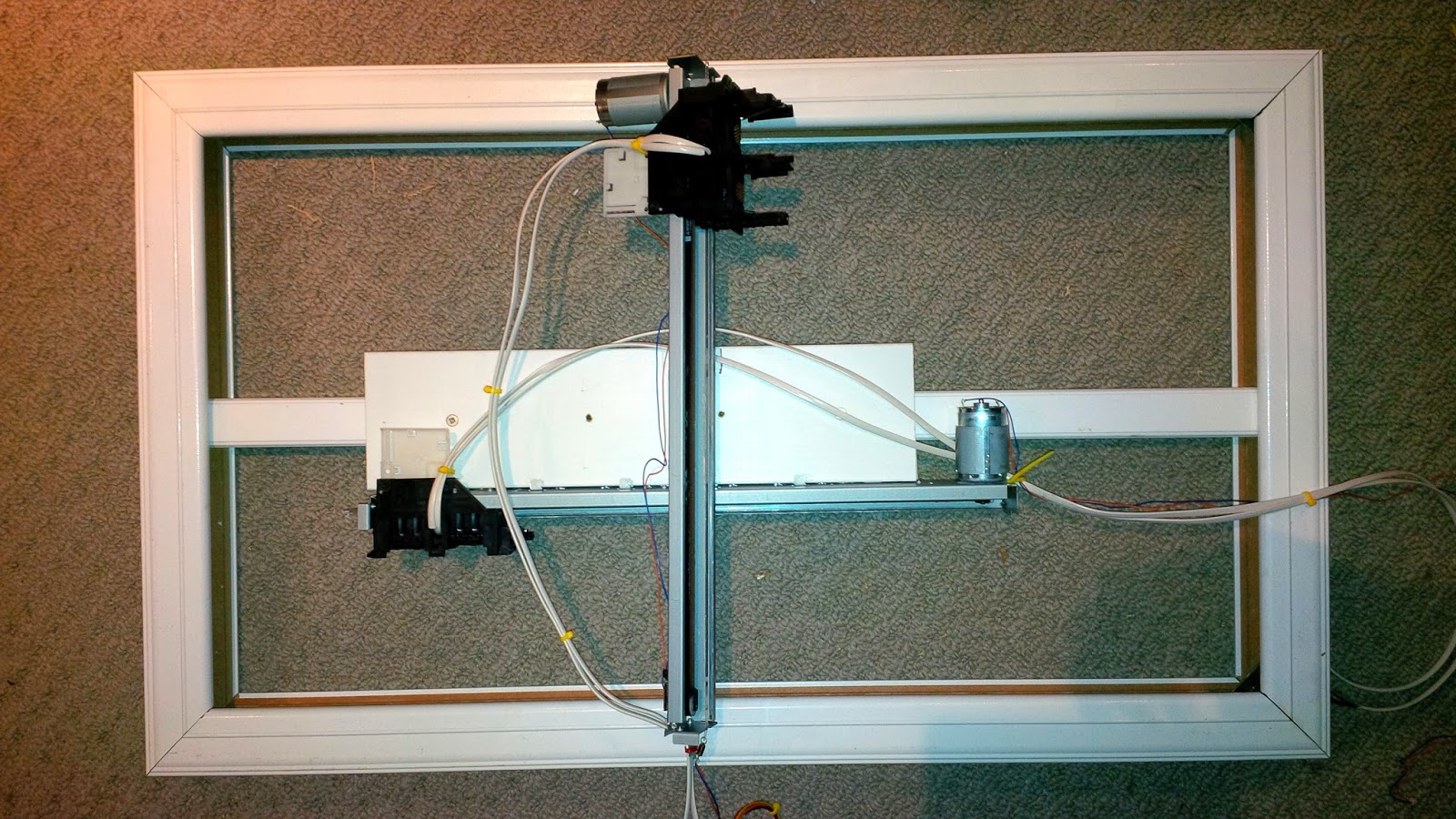
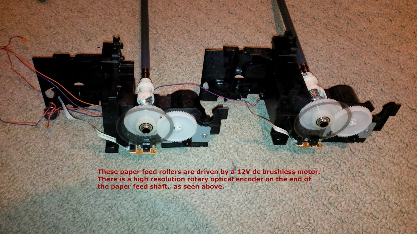
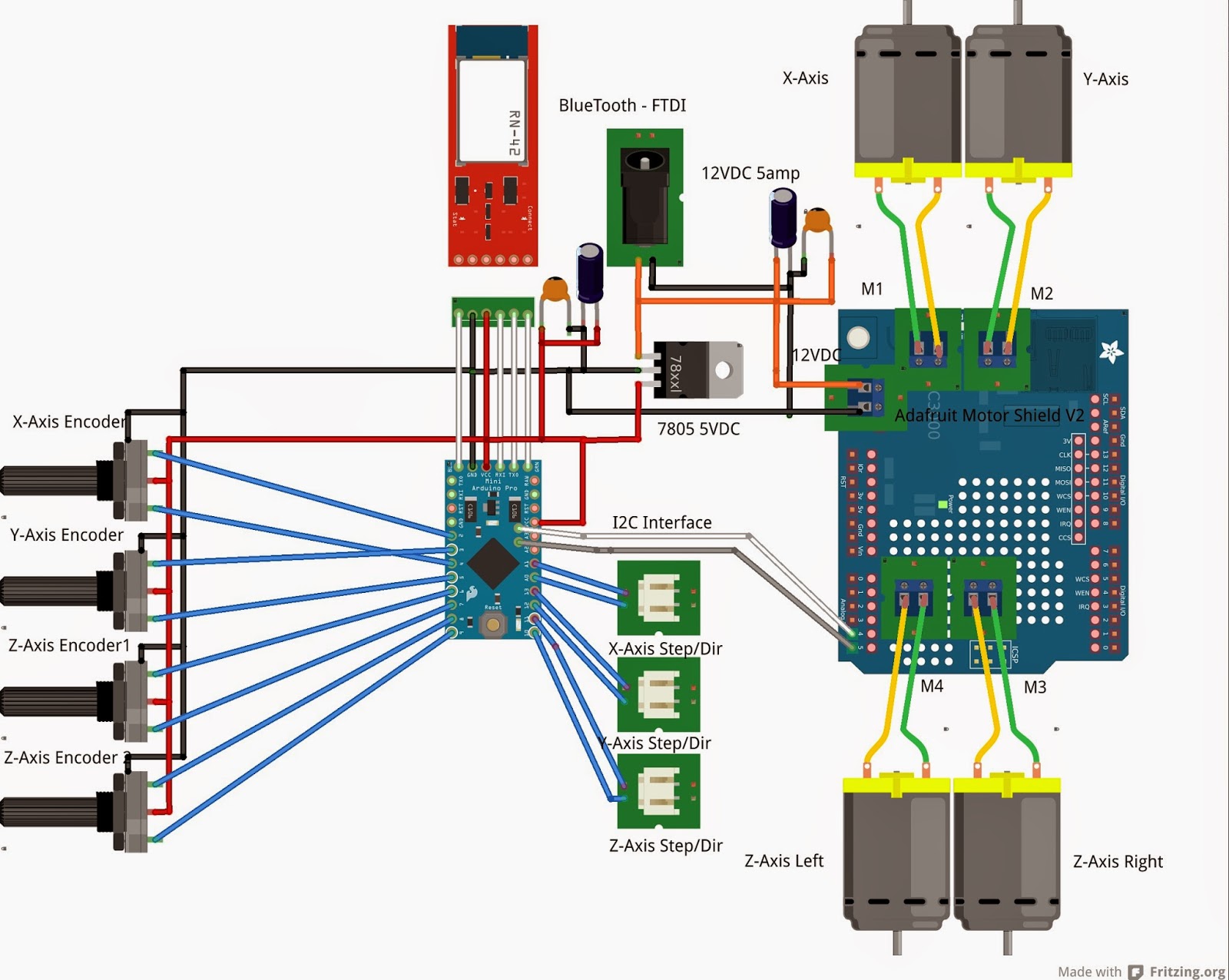
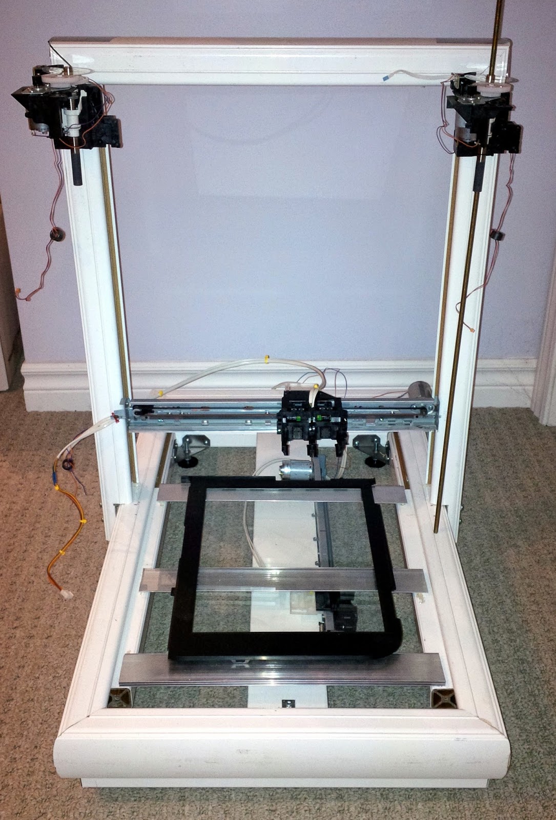
* This sketch allows you to run two salvaged printer carriages for X/Y axis using their
* linear encoder strips for tracking.
* This example uses the Arduino PID Library found at:
* https://github.com/br3ttb/Arduino-PID-Library/archive/master.zip
*
* Hardware Interrupt 0 on Digital pin2 is used to determine X-Axis position
* Hardware Interrupt 1 on Digital pin3 is used to determine Y-Axis position
* PinchangeInterrupt is used to identify the Zero Endstop for X and Y axis
*****************************************************************************************/
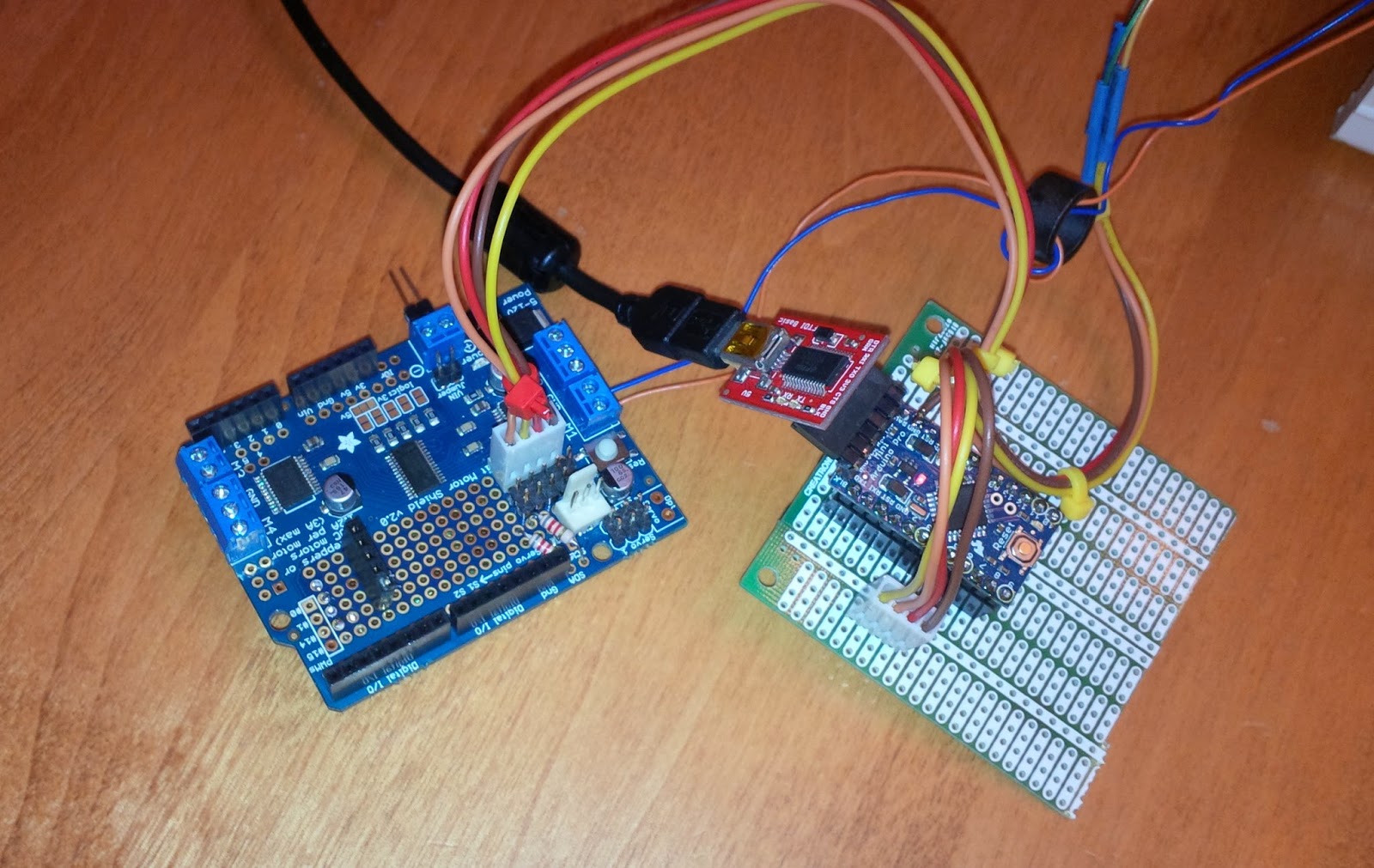
#include <Wire.h>
#include <Adafruit_MotorShield.h>
#include "utility/Adafruit_PWMServoDriver.h"
#include <PID_v1.h>
#include <PinChangeInt.h>
#define frontstop = 100 // Right most encoder boundary
#define backstop = 3600 // Left most encoder boundary
// Create the motor shield object with the default I2C address
Adafruit_MotorShield AFMS = Adafruit_MotorShield();
// Select which 'port' M1, M2, M3 or M4. In this case, M1
Adafruit_DCMotor *XaxisMotor = AFMS.getMotor(1);
Adafruit_DCMotor *YaxisMotor = AFMS.getMotor(2);
const int XaxisENCPinA = 2; // X-AXIS encoder 1 on pins 2 and 4
const int XaxisENCPinB = 4;
const int XaxisENDSTOP = 10; // Endstop photointerrupter for X-Axis
volatile double XaxisENCPos = 0;
const int YaxisENCPinA = 3; // Y-AXIS encoder 2 on pins 3 and 5
const int YaxisENCPinB = 5;
const int YaxisENDSTOP = 11; // Endstop photointerrupter for Y-Axis
volatile double YaxisENCPos = 0;
double XaxisSpd, YaxisSpd; // Carriage speed from 0-255
double XaxisPos, YaxisPos; // Current Carriage position
/*working variables for PID routines*/
// Tuning parameters
float KpX=0, KpY=0; //Initial Proportional Gain
float KiX=10, KiY=10; //Initial Integral Gain
float KdX=0, KdY=0; //Initial Differential Gain
double XaxisSetpoint, YaxisSetpoint; // Taget position for carriage
// Instantiate X and Y axis PID controls
PID XaxisPID(&XaxisPos, &XaxisSpd, &XaxisSetpoint, KpX, KiX, KdX, DIRECT);
PID YaxisPID(&YaxisPos, &YaxisSpd, &YaxisSetpoint, KpY, KiY, KdY, DIRECT);
const int sampleRate = 1;
long int reportTime;
void setup() {
Serial.begin(115200);
Serial.println("Linear Encoder Test 05-12-2014");
AFMS.begin(); // Set up Motors
XaxisMotor->run(BACKWARD); // Bring carriage to home position.
XaxisMotor->setSpeed(70);
delay(100); // Get endstop limiter working here
XaxisMotor->run(FORWARD); // Bring carriage to home position.
XaxisMotor->setSpeed(0);
YaxisMotor->run(BACKWARD); // Bring carriage to home position.
YaxisMotor->setSpeed(70);
delay(100); // Get endstop limiter working here
YaxisMotor->run(FORWARD); // Bring carriage to home position.
YaxisMotor->setSpeed(0);
attachInterrupt(0, doXaxisENC, CHANGE); // encoder pin on interrupt 0 (pin 2)
attachInterrupt(1, doYaxisENC, CHANGE); // encoder pin on interrupt 1 (pin 3)
PCintPort::attachInterrupt(XaxisENDSTOP,doXaxisEndstop,FALLING); //X-axis Endstop ISR
PCintPort::attachInterrupt(YaxisENDSTOP,doYaxisEndstop,FALLING); //Y-axis Endstop ISR
randomSeed(analogRead(0)); // Used to select random setpoints for testing
XaxisPID.SetMode(AUTOMATIC); //Turn on the PID loop
XaxisPID.SetSampleTime(sampleRate); //Sets the sample rate
YaxisPID.SetMode(AUTOMATIC); //Turn on the PID loop
YaxisPID.SetSampleTime(sampleRate); //Sets the sample rate
reportTime = millis()+2000;
}
void loop() {
uint8_t oldSREG = SREG; // Store interrupt status register
cli();
XaxisPos = XaxisENCPos;
YaxisPos = YaxisENCPos;
SREG = oldSREG; // Restore interrupt status register
// Temporary to create random X and Y axis setpoints for testing
if(millis() > reportTime) { // Only validate this every 2 seconds
if(XaxisPos == XaxisSetpoint && YaxisPos == YaxisSetpoint) {
// If both X-axis and Y-axis have reached their target - get new targets
XaxisSetpoint = random(200,3500); // Keep target within bounds of Endpoints
YaxisSetpoint = random(200,3500); // Keep target within bounds of Endpoints
}
reportTime = millis()+2000;
}
// Manage X-axis positioning
XaxisPID.Compute(); //Run the PID loop
if(XaxisSetpoint < XaxisPos) XaxisMotor->run(BACKWARD); // Determine direction of travel
else XaxisMotor->run(FORWARD);
XaxisMotor->setSpeed(XaxisSpd); // Apply PID speed to motor
// Manage Y-axis positioning
YaxisPID.Compute(); //Run the PID loop
if(YaxisSetpoint < YaxisPos) YaxisMotor->run(BACKWARD); // Determine direction of travel
else YaxisMotor->run(FORWARD);
YaxisMotor->setSpeed(YaxisSpd); // Apply PID speed to motor
}
/***************************************************************************************
The following code was taken from http://forum.arduino.cc/index.php?topic=41615.20;wap2
to utilize the fast port based encoder logic. Thank you Lefty!
please go there for a full explanation of how this works. I have truncated the comments
here for brevity.
***************************************************************************************/
void doXaxisENC() { // ************** X- AXIS ****************
if (PIND & 0x04) { // test for a low-to-high interrupt on channel A,
if ( !(PIND & 0x10)) { // check channel B for which way encoder turned,
XaxisENCPos = ++XaxisENCPos; // CW rotation
}
else {
XaxisENCPos = --XaxisENCPos; // CCW rotation
}
}
else { // it was a high-to-low interrupt on channel A
if (PIND & 0x10) { // check channel B for which way encoder turned,
XaxisENCPos = ++XaxisENCPos; // CW rotation
}
else {
XaxisENCPos = --XaxisENCPos; // CCW rotation
}
}
} // End of interrupt code for encoder #1
void doYaxisENC(){ // ************** X- AXIS ****************
if (PIND & 0x08) { // test for a low-to-high interrupt on channel A,
if (!(PIND & 0x20)) { // check channel B for which way encoder turned,
YaxisENCPos = ++YaxisENCPos; // CW rotation
}
else {
YaxisENCPos = --YaxisENCPos; // CCW rotation
}
}
else { // it was a high-to-low interrupt on channel A
if (PIND & 0x20) { // check channel B for which way encoder turned,
YaxisENCPos = ++YaxisENCPos; // CW rotation
}
else {
YaxisENCPos = --YaxisENCPos; // CCW rotation
}
}
} // End of interrupt code for encoder #2
void doXaxisEndstop() {
XaxisENCPos=0; // X-Axis Endstop indicates ZERO position
}
void doYaxisEndstop() {
YaxisENCPos=0; // Y-Axis Endstop indicates ZERO position
}